Semi-Autonomous Robot
As part of an embedded systems course my team and I built a robot from scratch designed to solve a robotics competition. The goal was to navigate toward a bright light source in the middle of a square table while avoiding collisions with walls in the shortest time possible.
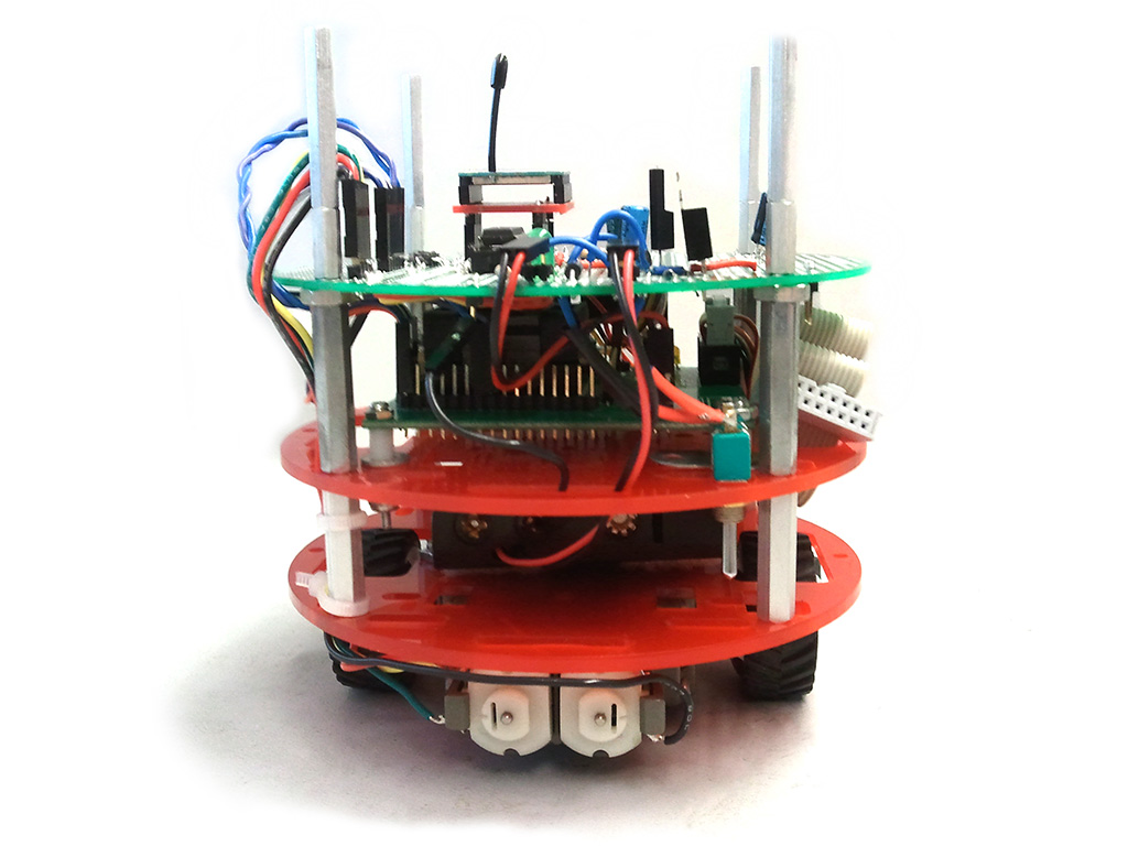
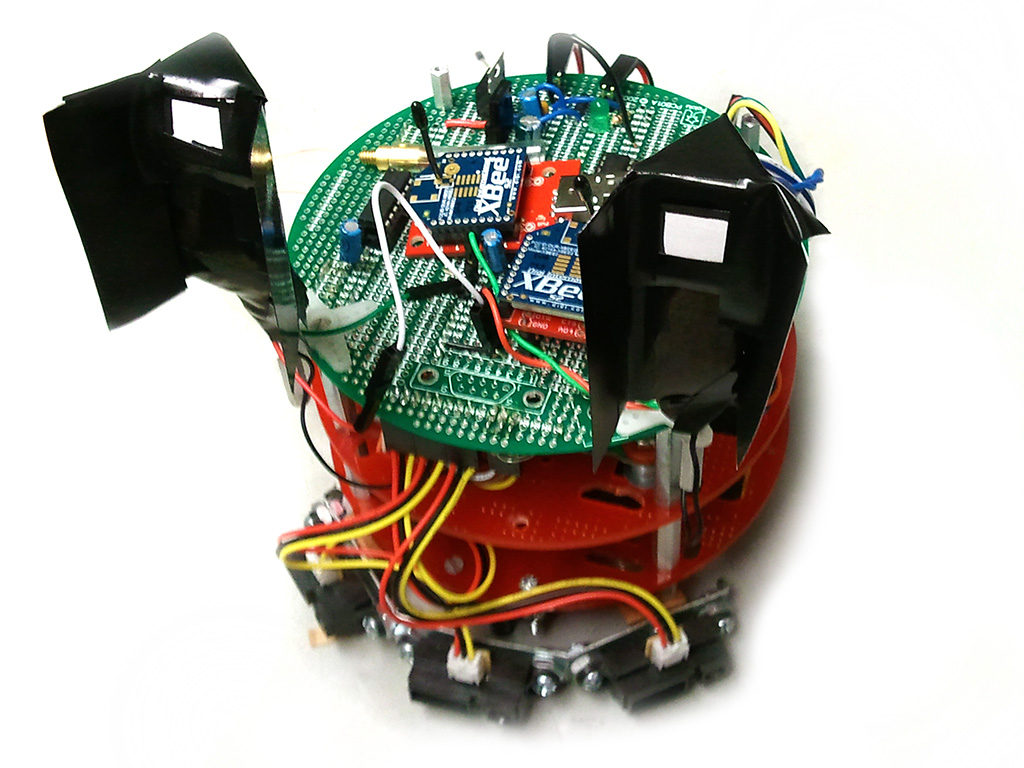
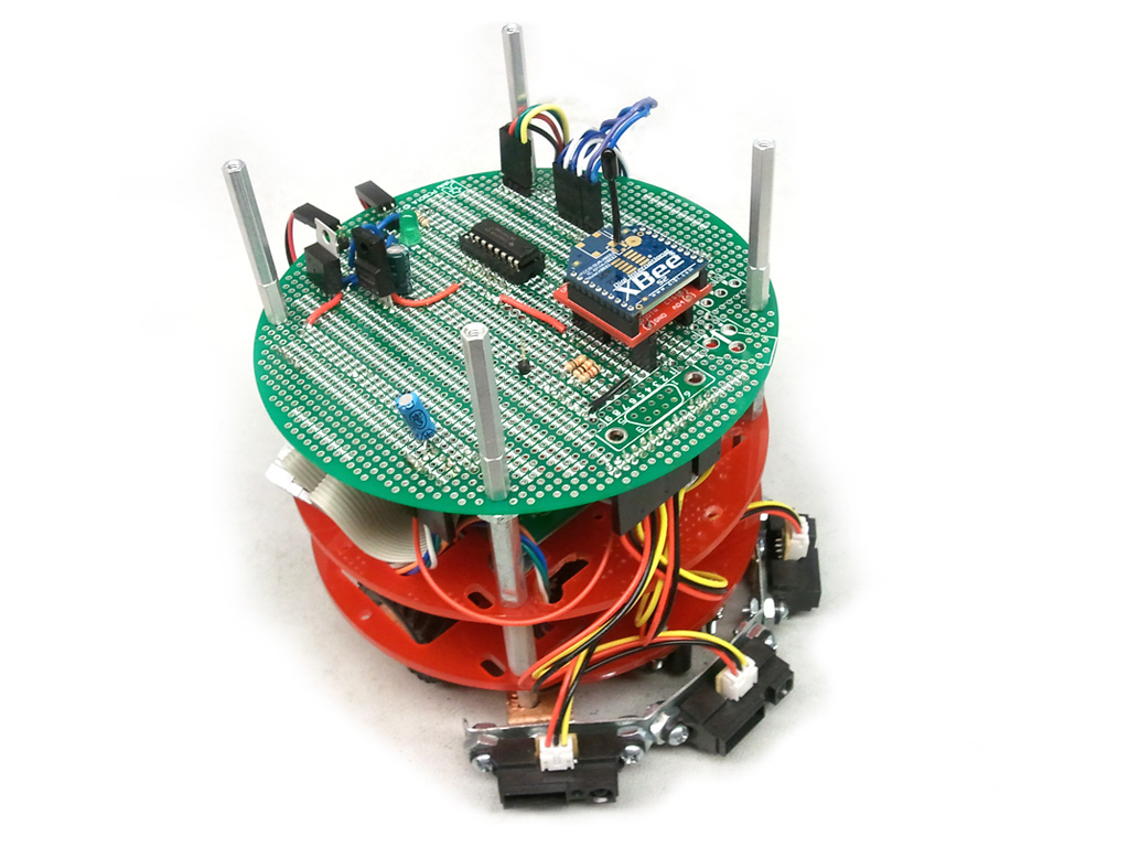
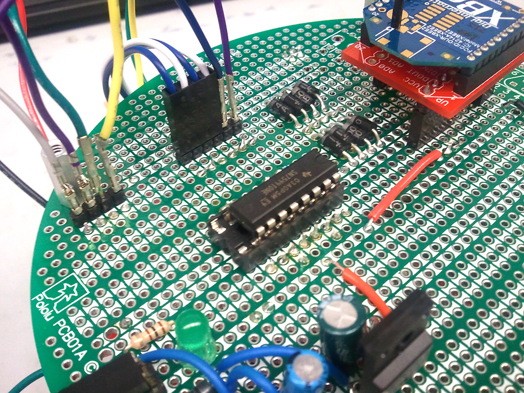
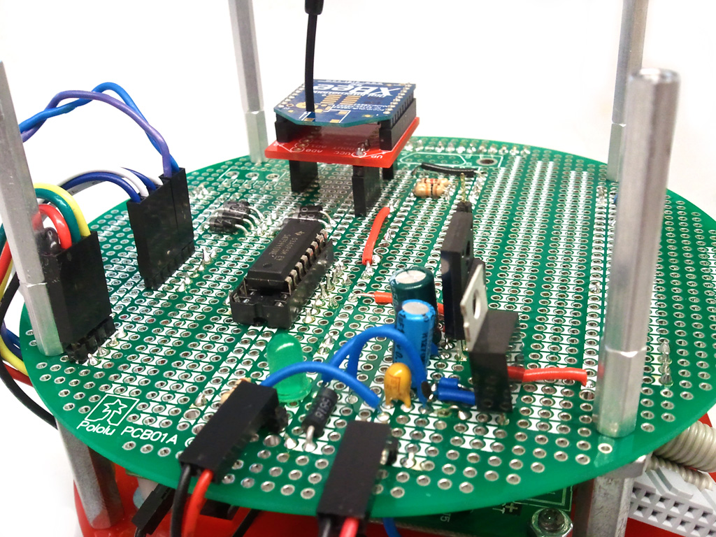
Staring from not much more than a bag of parts, we constructed the system over a series of 3 months. The basic shape was a tower stacked with 3 discs, two acrillic for support and a top circular PCB where all electrical components were mounted. Between the bottom discs we mounted a 4x AAA Battery pack, and between the top discs we mounted the microcontroller QFP ZIF socket PCB. On the bottom we mounted a TOMY gearbox with wheels.
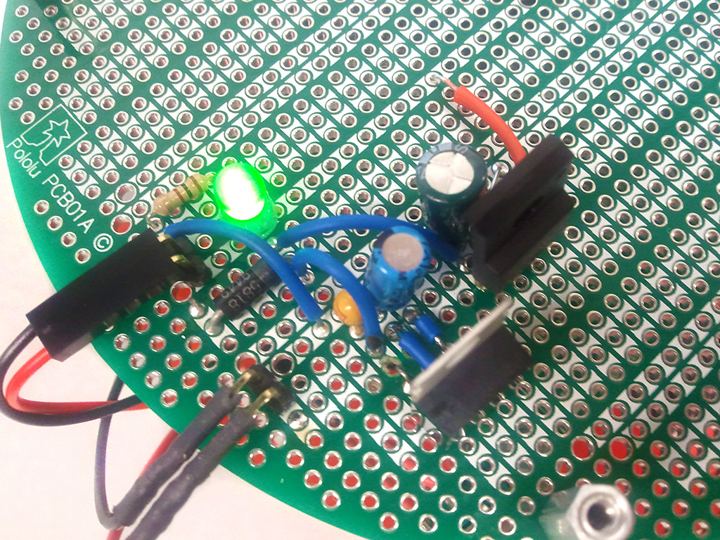
We designed a simple voltage regulator circuit to regulate the 6V provided by the battery into the 5V and 3.3V needed for all the onboard hardware. Diodes were added for reverse voltage protection and power-on indication.

The microcontroller chosen for this system was a 16-bit TI MSP430F2619. The MSP430 provided us with an ample amount of I/O while also including low power modes. The entire embedded program was written in C using organized coding conventions.
The motors were driven using a H-bridge controlled through PWM signals from the microcontroller. We were able to move forward and backward and obtain rotation at various speeds. Due to the high levels of current drawn by the motors, we isolated the grounding for this section of the circuit.
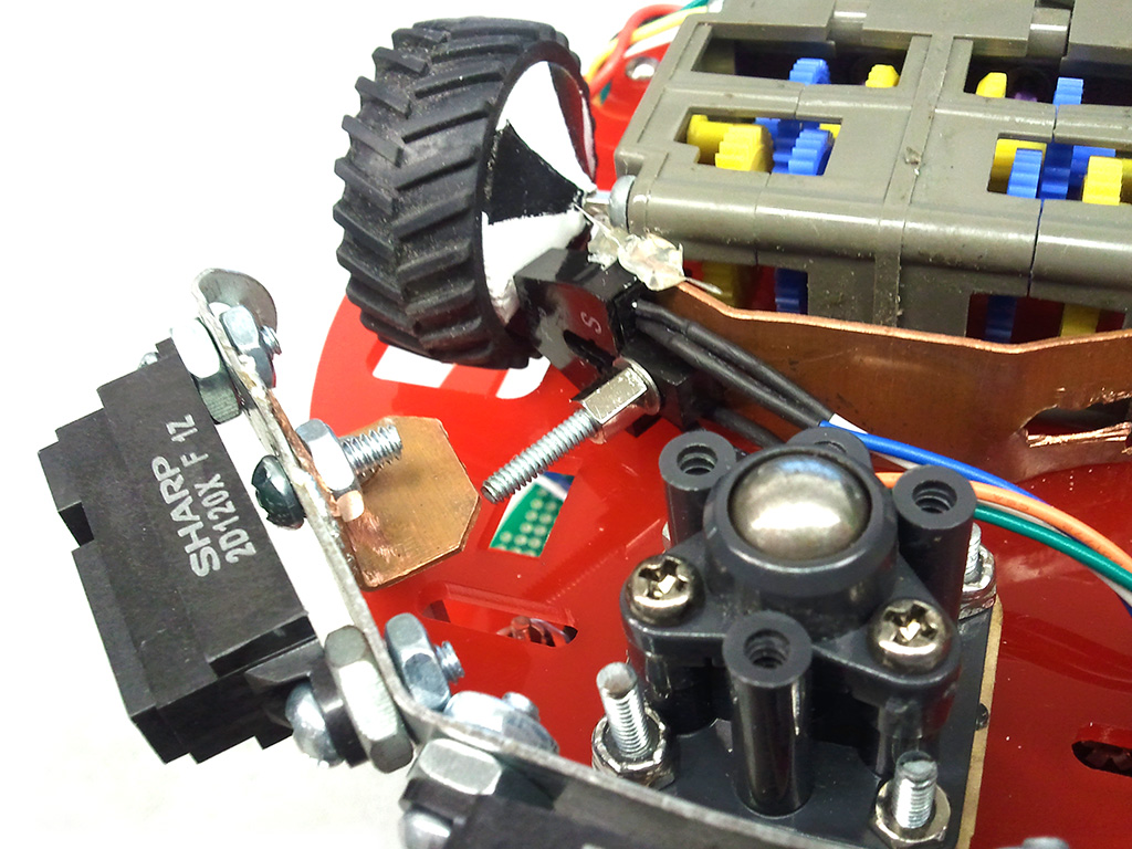
The H-bridge fed into two motors which drove a gearbox configured in the slowest ratio. A shaft encoder was also included on the wheel however it ended up not being necessary.
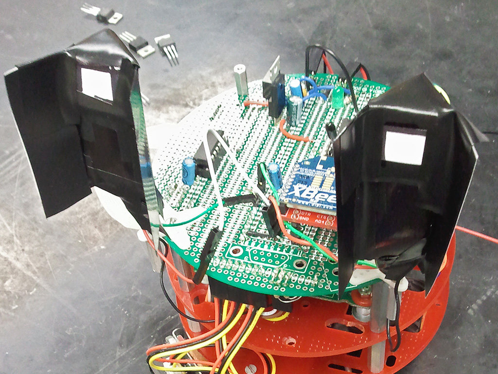
The light sensors used converted light intensity to frequency. We detected the frequency using a digital input interrupt. Because the frequency outputted by the sensors exceeded that which our microcontroller could handle, we placed filters over the sensors to lower it. Two of these sensors were used, both placed forward with blinders over them to lower the input angle. By comparing the frequency of the two sensors, the light source can be identified.
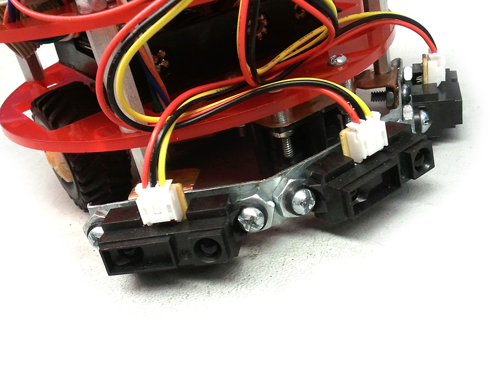
Three infrared distance sensors were mounted on the front of the robot, one facing forward, and the other two angled towards the left and right. Using these, we could identify if a wall or other object was close to the robot to avoid collisions.
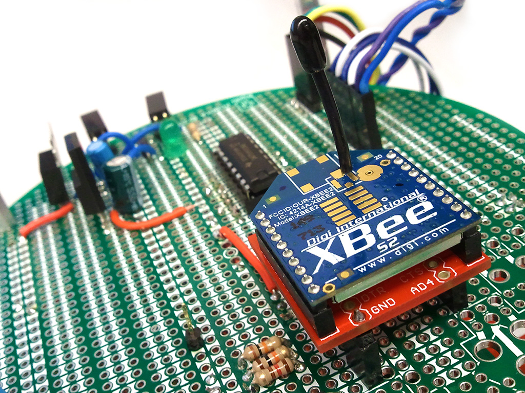
The communication used bidirectional wireless transmission for issuing commands to the robot and receiving status data from it. Two XBee devices were used in transparent serial mode, one on the robot and one on a PC. A simple data transmission frame was developed to transmit ASCII data commands including error detection using a XOR-based CRC. A command typically involved a single ASCII word followed by a numerical argument. On the robot, the XBee communicated with the microcontroller over Serial UART using interrupt driven data buffering and decoding. The decoding of this command was processed within the microcontroller which matched the command with an internal list to determine the behavior.
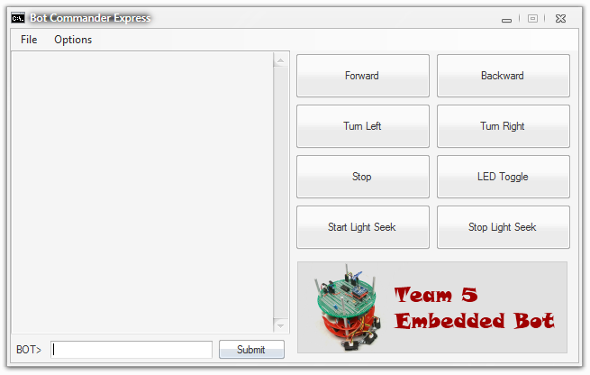
Data was also sent from the robot to the PC, though this was used primarily for debugging. On the PC, the XBee was connected to a Serial to USB coverter. A control application console was developed in C# to allow the user to type input commands and display and buffer incoming data.
The algoritm we developed was rudimentary, but was able to solve the maze in most cases. Thresholds were setup for the distance sensors. If the two sensors had a high similar value, the light source is directly in front and the robot should move forward. If one is much greater than the other, the robot should turn in the direction of the greater valued sensor while moving forward. If both sensors were below a threshold, then only ambient light is being detected and the robot will spin until one of the previous conditions is satisfied. To detect the walls, we read the values from the sensors while moving. If a side sensor detected a distance below 8cm, the robot would rotate in the opposite direction of the sensor until the sensor was above 9cm. We set the priority for the wall avoidance behavior above the light seeking behavior. This algorithm caused the robot to jitter while moving along the wall, but generally was still able to locate the light except in situations where it was led into a dead end alley. Such situations were rare, and as such the robot was able to meet the requirements and operate successfully.